Design of Campus Navigator
N.Bharathi1
K.S.Hema Priya2
1Professor, Dept. of Electronics & Instrumentation Engineering Velammal Engineering College, Chennai, India |
AbstractObjective: Designing a handheld campus navigator module is designed for a specific campus to move around easily without any external help. Methods: The geographical position of the building is obtained based on the data received using GPS device and with these data, a location tracking algorithm is framed. Therefore, user will be provided with the location based information of each building in a particular campus to move from one pin-point interest to another. Analysis: Now-a-days mobile applications are used for navigation purpose. But in many places like educational institutions, industries etc., mobile phones are not allowed inside the campus.so a handheld module are designed to navigate inside a particular campus. This paper deals with the design of campus navigator for a college campus. Improvement: Feasibility of using a GPS based handheld guide, its benefits and drawbacks for a campus drive is clearly explained in this paper. |
Licensed: |
|
Keywords: |
1. Introduction
In the past few years we have seen an exciting race for miniaturization of computing devices. Tasks that were once performed by instruments that took up large space and were not portable can now be accomplished on a device that fits into a human hand1.A handheld device is a small computing device which has a display screen with touch input or a keyboard. These handheld devices can also have Wi-Fi, Bluetooth, and GPS facilities2.
Many handheld devices also contain sensors like accelerometer, magnetometer and gyroscope which can detect the orientation and motion. They are widely used for digitizing notes, recording signatures, assessment management etc.
There are many navigation applications such as Yahoo Maps, Google Maps and Map quest that provides its users with directions from one location to another3. However, these applications are not able to provide routes that are as precise as an on-campus path would require. A handheld device is developed for a particular campus based on Global Positioning System (GPS) navigation system. GPS navigation is a commonly used assistant during a trip4. By using this navigation system, travellers can quickly arrive at their destination when in an unfamiliar area with complete ease. GPS tracking devices are capable of telling the user his/her approximate latitude, longitude, altitude, time and number of satellites seen5. Therefore this concept is used to design a navigation system for a college campus, theme parks etc.
A campus is a complex infrastructure. Especially new students and people who are there for the first time find it very difficult to orientate themselves and find various places. Even if there are maps at a few points on the campus, users do not have continuous guidance to get to their desired destination. They can try to find out a way to get to their destination using these various static maps, but as they start to walk in the target direction they have no help. Systems for pedestrian navigation are quite hard to find. Therefore to help freshmen and other inexperienced people orientate themselves to a particular campus and to find different places on the campus a Campus Navigator is designed6.
In this paper a navigation system for a college campus is developed. The campus is spread over 35 acres of land. The campus has many blocks. Many departments are integrated in a single block. Few of the blocks are even provided by walkways. Our Campus Navigator handheld device enables users to obtain routes to the various blocks of the campus that are much more detailed than an existing commercial application can provide.
2. Hardware Description
The goal of our project is to design a campus navigator system. A GPS device, a keypad and a LCD display are interfaced to a micro controller. Arduino Atmega 328P is chosen as the micro controller which has 14 digital pins (out of which 6 can be used as PWM output),6 analog pins, 5v operating voltage , 32 KB flash memory, 2 KB SRAM, 16 MHz clock speed. Ublox Neo 6M is used as a GPS device it navigates down to –162 dBm and –148 dBm cold start, Faster acquisition with Assist, configurable power management, hybrid GPS/SBAS engine
WAAS, EGNOS, MSAS, anti-jamming technology, simple integration with u-blox wireless modules. A 16x2 LCD display is used to display the current position and designation, it can display 16 characters per line and there are 2 such lines. In this LCD each character is displayed in 5x7 pixel matrix, it operates on a supply voltage of 5V. This LCD has two registers, namely, Command and Data. The command register stores the command instructions given to the LCD. A command is an instruction given to LCD to do a predefined task like initializing it, clearing its screen, setting the cursor position, controlling display etc. The data register stores the data to be displayed on the LCD. The data is the ASCII value of the character to be displayed on the LCD. The below Figure 1 shows how the microcontroller is interfaced with LCD display and GPS module. The ground and supply pins are connected to both LCD and GPS module from the microcontroller. Rx and Tx pin of the controller is connected to Tx and Rx of GPS. Pin 4 to 6 are used as 4bit address lines are used to transmit the data to LCD. Pin 11 is used as the enable pin for LCD and pin 12 is used as selection pin (i.e. data/command line for LCD)
3. Map View
A college campus consists of complex buildings especially for new students and people who are visiting for the first time. They may have hard time to orientate themselves and locate places and buildings. The campus of the Velammal Engineering College (VEC) is spread over 35 acres of land. The campus has many different blocks. Many departments are integrated into a single block. The detailed description about the departments, laboratory, and computer center present in each blocks are shown below
- DR. ABDUL KALAM BLOCK
- JUSTICE MUTHUSWAMY BLOCK
- FOUNDER CHAIRMAN BLOCK
- BILL GATES & RENGANATHAN BLOCK
- NALA BLOCK
- NEW GIRLS HOSTEL
- T.V.SUNDARAM IYENGAR BLOCK
- OFFICE
- ARIGNAR ANNA BLOCK
- VIKRAM SARABHAI BLOCK
- DR. VISVESWARAIAH BLOCK
The Figure 2 depicts the map of the campus that has to be drawn as a program in microcontroller memory and a location tracking algorithm has to be framed and according to this algorithm different routes will be framed between nodes, blocks of the campus and the user will be successfully navigated to the destination correctly. The whole campus has 14 blocks and 7 nodes. User has to navigate between these nodes and blocks. From the above figure it can be clearly understood the entrance of each block is named as E and the point where user needs the instruction to take left or right is consider as node N and D is assign for dead ends no further movements, and this shows how the blocks and nodes are constructed in the college campus for which location tracking algorithm has to be framed. The tracking will be done by comparing the two coordinates of source (current location) and destination (user input), the difference between the values are known to the controller this difference helps to find the shortest path inside side the campus. As the user moves the current position is updated so the difference between the coordinates also gets updated. Thus tracking is done in this way to display the path. The tracking algorithm helps a person to reach his/her destination accurately
4. Description
Global Positioning System (GPS), a tracking device is capable of informing the user their current position is interfaced to Arduino Atmega 328P microcontroller which can guide a person where they want to move around within the campus, destination point is taken from the user using keypad. By getting the current position and destination, a location tracking algorithm is framed based on which the micro controller is programmed that will navigate the user in correct path7.
When the user select the destination place from the given options (keys in keypad), that will be given as an input to the microcontroller, initial current location of the user in terms of GPS co-ordinates is found and fed to the microcontroller. As the user passes by each node or block of the campus its GPS co-ordinates are fetched and fed to the microcontroller and it is compared with the already fed GPS co-ordinates and the waypoints in the pathway will be displayed continuously in the display unit. The Figure.3 shows the flowchart about how the device is programmed and how it navigates the user in correct path.
5. Simulation & Results
When GPS is connected to arduino microcontroller the coordinates will be displayed in standard format like RMC, GGA etc. in those Recommended minimum coordinates (RMC) is seen in the serial monitor is decoded. For decoding RMC need a conversion of degree after conversion the latitude and longitude is taken and displayed in the LCD that is shown in the Figure 4.
Thus GPS co-ordinates for different blocks and different nodes have been taken using GPS device. The GPRMC values are taken from the device and they are decoded and its respective latitude and longitude co-ordinates are found out this. These values are fed into microcontroller and when the GPS module receives the GPS co-ordinates tries that is interfaced to the microcontroller receives latitude and longitude points of respective block or node when the user reaches the place the real time co-ordinate points are compared to the ones that are already fed into microcontroller memory and when the co-ordinates matches it displays the current location the user is at. Table.1 and 2 shows the GPS co-ordinates of each block and each node that was taken using Ublox Neo 6m. Figure 3 shows the co-ordinates of the block are displayed in display device similarly the latitude and longitude of each block is noted.
| Block | GPS Co-Ordinates |
|
Latitude |
Longitude |
|
| EIE Start | 1308.94 |
8011.47 |
| EIE End | 1308.92 |
8011.46 |
| Boys Hostel | 1308.92 |
8011.46 |
| Admine Block | 1309.01 |
8011.47 |
| EC/EEE/IT/CSE | 1308.09 |
8011.51 |
| Gate | 1309.04 |
8011.49 |
| PG/ES/PS | 1308.97 |
8011.51 |
| Office | 1308.97 |
8011.51 |
| Auto/Production | 1308.95 |
8011.52 |
| Civil Block | 1308.93 |
8011.52 |
| Mechinical | 1308.92 |
8011.52 |
| Library | 1308.88 |
8011.53 |
| Girls Hostel | 1308.83 |
8011.48 |
| Canteen | 1308.8 |
8011.53 |
| Node | GPS Coordinates |
|
Latitude |
Longitude |
|
| EIE Node | 1308.93 |
8011.48 |
| ANNA Audit Node | 1308.94 |
8011.47 |
| Admine Node | 1309.99 |
8011.47 |
| Temple Node | 1309.037 |
8011.5 |
| Parking Node | 1309.03 |
8011.51 |
| Civil Node | 1308.94 |
8011.52 |
| Canteen Node | 1308.84 |
8011.48 |
6. Conclusion
GPS co-ordinates for each block and node was taken and when we look at the latitude and longitude points that is shown in the tables 1 and 2 we can infer that same GPS co-ordinates reflects for two different nodes or two or more different blocks. This problem will confuse the microcontroller or may lead microcontroller to dislocate the place and may mislead the user. So, in order to rectify this problem advanced tracking technique can be used to track the correct location and devices like beacons or low cost transceiver is used for accurate location tracking. For a small campus the coordinates for each block is falls in the same values if the distance between the blocks increase then the accuracy of the system will also increase (i.e. the GPS value will be unique for each block) so tracking between two points will be more accurate, so this system is applicable for large campus like IIT, MIT campus in Chennai, etc. For a small campus indoor positioning sensor, sensor networks, beacons are used to navigate accurately. Thus this system is economical only for large campus area.
References
[1] Tao, Z. & Xiaosu, X. (2010). A new method of seamless land navigation for GPS/INS integrated system in Sci Verse Science Direct.
[2] Ching, W., Teh, R.J., Li, B. & Rizos, C. (2010). Uniwide WiFi based positioning system in IEEE International Symposium on Technology and Society (ISTAS), pp. 180–189.
[3] Wang, J. & Lin, Z.A. (2010). General 3D campus navigator system in IEEE/ACIS International Conference on Computer and Information Science. pp: 1074–1078.
[4] Chou, T.S.A. (2008). Campus navigation and parking assistant system in IEEE International Conference on Systems, Man, and Cybernetics, Taipei, Taiwan, October 8-11, 1: 631–638.
[5] Rosen, I. (2012). Real-time GPS track simplification algorithm for outdoor navigation of visually impaired in Journal of Network and Computer Applications.
[6] Bangare, P. S., Gandhi, P. N., Diwate, S. B., Gujar, R. S. & Bangare, S. L. (2013). The campus navigator: An android mobile application in. International Journal of Advanced Research in Computer and Communication Engineering, 3(3).
[7] Wang, C.S. & Hong, C.Y. (2009). A location and interest based peer to peer virtual navigation system in International Conference on the Applications of Digital Information and Web Technologies, pp. 676–681.
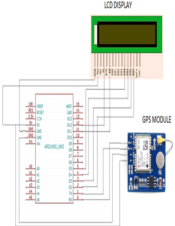
Figure-1. Microcontroller interface.
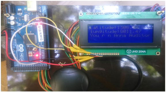
Figure-4. Snapshot of the Result.
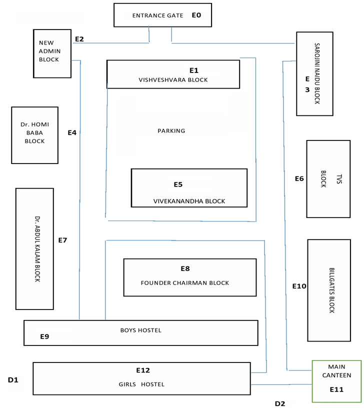
Figure-2. College map view.
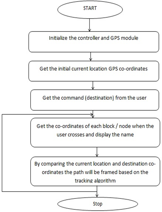
Figure-3. Program flow.