Industrial Drive Performance Analysis with Direct Matrix Converter
K.V.Kandaswamy1
M.S.Sharmila2
1Professor, Dept. of Electronics & Instrumentation Engineering, Velammal Engineering College, Chennai, India |
AbstractObjective: The performance of induction motor using various optimization techniques has been analysed. SVM based PID control technique is implemented to analyse the performance for each switching combination. Methods: There are many methods that are used to control matrix converter in scalar and vector control method. In this paper, the performance of induction motor is analysed using Space Vector Modulation (SVM). Findings: SVM technique is mainly used because of its advantages like higher voltage transfer ratio, lower Total Harmonic Distortion (THD) and unity power factor. A three phase matrix converter is used which is an AC-AC power converter topology, where the output voltage and frequency can be changed and it allows 27 different switching states. Improvement: Many control techniques are available to tune the matrix converter effectively and PID controller tuning is used to select the best switching combination for the required output of induction motor. |
Licensed: |
|
Keywords: |
1. Introduction
A three phase induction motor is an AC electric motor, for which the performance is analyzed. The three-phase induction motor, also known as an asynchronous motor, is the most commonly and widely used type of motor in industrial applications. Squirrel-cage electric motor is most widely used and in this paper the performance of an induction motor is analyzed in Simulink with the help of a matrix converter, which is an ac-ac converter. It consists of nine bi-directional switches, so that any one of the three input phases can be connected to the three output line, to form the switching combinations. The switches have to be controlled in such a way that the average output voltages are a set of three-phase sinusoids of the required frequency and magnitude. The switching combinations of matrix converter are used to drive the three-phase induction motor and thus the analysis of simulation of output voltage, current – rotor and stator, rotor speed and electromagnetic torque are made. An input voltage source of 100V peak amplitude is given with a simple LC filter to reduce the switching harmonics and to obtain the output simulation results.
Different tuning methods such as Ziegler-Nichols method, Auto tuning method, Cohen-Coon method etc. are available for selecting switching configuration. In this paper, normal PID tuning method is used to control the switch according to the error obtained. Among many techniques, SVM technique is used here.
Various methods such as control of Matrix converter 1, SVM multilevel matrix converter 2, Modulation method for matrix converter 3, Direct control methods of matrix converter 4have been proposed in the past for simulation of induction motor.
This paper is to analyse the performance of an induction motor in MATLAB using SVM technique and matrix converter and the simulation results shows the analysis of output of an induction motor. This paper is organized as follows; Matrix converter is briefly explained in section 2; Space Vector Modulation is presented in section 3; SVM technique for three phase induction motor using PID controller is presented in section 4; simulation results are given in section 5; and final section concludes the paper.
2. Three Phase Matrix Converter
Matrix converter, also known as forced commutated cycloconverter, is an AC-AC power converter topology that converts one AC waveform to another AC waveform, in which the output frequency and voltage can be set arbitrarily. It can act as an alternative to indirect power converter systems. Matrix converter mainly consists of nine bidirectional switches based mainly on the semiconductors. It is a single stage converter with an array on m x n bi-directional switches which connects the m-phase voltage source to n-phase load where number of inputs must be at least three and number of outputs can vary from one to theoretically infinity. Any output phase in it can be connected to any input phase.
Matrix converter is the combination of bidirectional semiconductor switches and Bipolar Junction Transistor (BJT) is the most commonly used controlled switch. Matrix converters have no limit on output frequency due to the fact it uses semiconductor switches with turn-off capability. Some of the advantages of this converter are providing bidirectional power flow, compact design due to the absence of DC link capacitor and reduced number of switches.
Each switch is characterized by a switching function which is defined as follows, where phase K of the input stage can be connected or disconnected to phase j of the load5.Output voltages can be obtained by a proper combination of the switches6.
Control of the matrix converter must follow the basic two rules. One is, any two input terminals should never be connected to same output line as to prevent short-circuit, because the Matrix Converter is fed by a voltage source. The other is, an output phase should never be an open-circuit, which leads to the over-voltage. When these two rules are followed, the 3 x 3 matrix converter allows 27 different switching states among the 512 possible switching combinations7.
3. Space Vector Modulation
SVM is used for the control of pulse width modulation (PWM) and many SVM techniques are used that result in different computational and quality requirements. SVM helps in the reduction of total harmonic distortion (THD) and it utilizes about fifteen percent of the available bus voltage, therefore increases the efficiency of motor operation and it provides greater flexibility in the choice of switching vector for input current and output voltage control.
Space vector representation is used to express three phase variables. For a small time interval, the approximation of the reference voltage vector can be done by a matrix converter set of stationary vectors. If this time interval is the sample time, then at next sampling instant a new set of stationary voltage vectors is created when there is a rotation of the reference voltage vector to a new angular position.
Space Vector Modulation (SVM) is defined as the approximation of an arbitrary vector in the d-q vector spaces, which an inverter generates, using the nearest three voltage vectors. The nearest three vectors are to be chosen by determining the triangle in which the desired voltage vector resides within the vector space8.The necessary on-duration of each of the vectors can be determined by Equations 3 and 4. These state that, V*, the demand vector is defined as the sum of the chosen three vectors (V1, V2, V3) which is multiplied by their on-durations (d1, d2, d3) and this on- durations must fill the complete cycle.
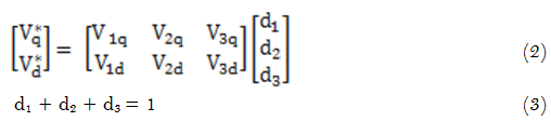
Equations 2 and 3 together produce Equation 4. Equation 4 can then be rearranged to obtain Equation 5. This expression gives the vector duty cycles in terms of the desired voltage vector and then the three nearest voltage vectors and the switching combinations using SVM are obtained.
4. SVM Technique for Three Phase Induction Motor Using PID Controller
This paper deals with the performance analysis of an induction motor using SVM technique. Space Vector Modulation (SVM) technique is the important PWM technique for the control of AC motors. It has been shown to reduce the harmonic distortion in the outputs and to provide more efficient use of supply voltage. Also, the switching configurations are obtained from the SVM technique as well. A PID controller, among the other available controllers, is used to select the necessary switching for the induction motor. An input voltage of 100v peak amplitude is given as supply and an LC input filter is used to reduce the switching harmonics that are present. A matrix converter, made of bidirectional switches, that helps in direct AC-AC conversion is used and most matrix converter applications currently use IGBT devices and diodes to create the power circuit. Bidirectional switches are constructed from available unidirectional devices. A significant advantage of a matrix converter topology is in the input filter size. A typically sized input inductor for a matrix converter will almost be smaller than the equivalently rated input inductor of a PWM rectifier. So, the matrix converter finds a wide application. Thus the analysis of output voltage, output current – rotor and stator, rotor speed and output electromagnetic torques are made. The block diagram of an SVM based induction motor is shown below in Figure 1. In this paper, the analysis is made for the output rotor speed using SVM technique.
5. Simulation Results
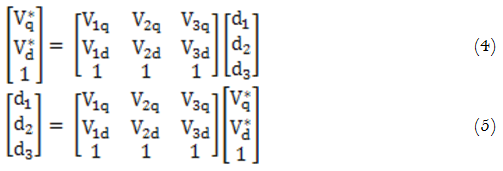
Output Voltage Plot
The output voltage plot of SVM technique for a matrix converter based induction drive is shown in Figure 2.
Figure-2. Output voltage plot.
Output Current Plot
Starting current of induction motor will be normally 8 – 10 times higher than the motor’s rated current because before starting, the motor will be at rest. Also the back emf due to the rotation of the motor will be at zero during rest condition and hence the motor draws high starting current. The output rotor current and stator current plot of SVM technique for a matrix converter based induction drive is shown in Figure 3 and Figure 4 respectively.
POWER CALCULATION
For rotor:
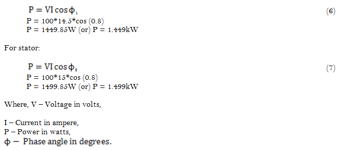
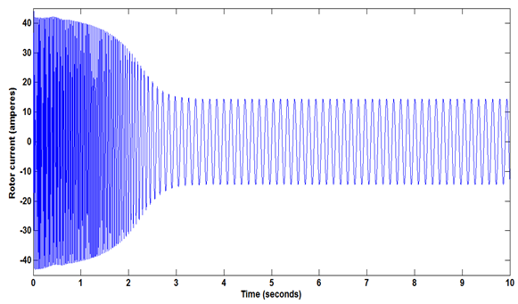
Figure-3. Output rotor current plot.
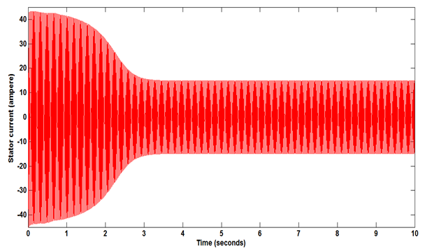
Figure-4. Output stator current plot.
Rotor Speed Plot
The output rotor speed plot of SVM technique for a matrix converter based induction drive is shown in Figure 5.
Vout = Kω (8)
Where, K – constant,
ω – Motor speed (ω = 2πN/60).
Therefore,
Vout α 2πN/60 (9)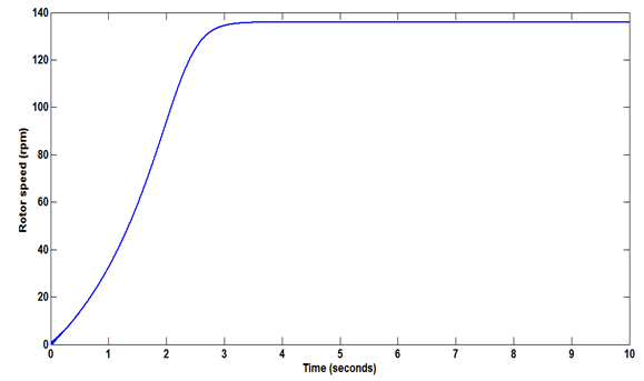
Figure-5. Output speed plot.
Electromagnetic Torque Plot
The output torque plot of SVM technique for a matrix converter based induction drive is shown in Figure 6.
T = Pm / ωm (10)
Where, Pm is the mechanical power developed,
ωm is the motor speed.
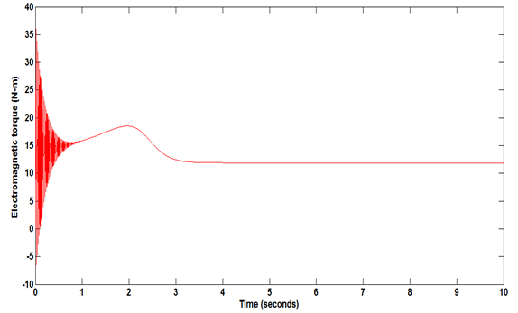
Figure-6. Output electromagnetic torque plot.
6. Conclusion
SVM technique is used for a matrix converter based induction motor and PID technique is used for tuning, which is modelled using MATLAB Simulink. Simulation results demonstrate the performance of SVM based induction motor. In progression of the project, the performance of output voltage, output current – rotor and stator current, rotor speed and electromagnetic torque for a three phase induction motor will be analyzed using other different optimization techniques.
References
[1] Yusoff, S., De Lillo, L., Zanchetta, P. & Wheeler, P. (2012). Predictive control of a direct AC/AC matrix converter power supply under non-linear conditions. 15TH International Power Electronics and Motion Control Conference, EPE-PEMC, ECCE Europe.
[2] Lee, M. Y., Wheeler, P. & Klumpner, C. (2010). Space-vector modulated multilevel matrix converter. IEEE Transactions on Industrial Electronics, 57(10): 3385-3394.
[3] Klumpner, C., Blaabjerg, F., Boldea, I. & Nielsen, P. (2006). New modulation method for matrix converters. IEEE Transactions on Industry Applications, 42(3): 797-806.
[4] Boll, J. & Fuchs, F.W. (2005). Direct control methods for matrix converter and induction machine, Institute of power electronics and electronic drives, Christian – Albrecths – University of Kiel, Germany.
[5] Karaca, H. & Akkaya, R. (2012). Modeling, simulation and analysis of matrix converter using matlab and simulink. International Journal of Modeling and Optimization, 2(3): 328-332.
[6] Rodriguez, J., Silva, E., Blaabjerg, F., Wheeler, P., Clare, J. & Pontt, J. (2005). Matrix converter controlled with the direct transfer function approach: Analysis, modelling and simulation. International Journal of Electronics, 92(2): 63-85.
[7] Ebubekir, E., Yetkin, T. & Sedat, S. (2005). Modelling and simulation of matrix converter using space vector control algorithm, Computer as a Tool, EUROCON. The International Conference on, 2, 2005.
[8] Mohammed, T.L., Muthanna, J.M. A-K. & Ahmed, I.A-S. (2011). Space vector modulation direct torque speed control of induction motor. 2nd International Conference on Ambient Systems, Network and Technologies, Elsevier Science.
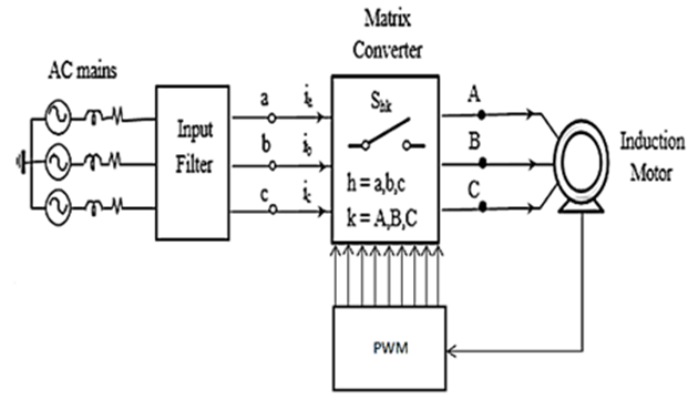
Figure-1. Block diagram of SVM based induction Motor.
`