Study, Development and Application of a Prosthetic Foot for a Transtibial Amputation of Traumatic Etiologic
Julia Alvarinho1
Jose Pedro Fulgencio2
Nuno Soares Domingues3*
1,2,3Polytechnic Institute of Lisbon, Lisbon Higher Institute of Engineering, Lisbon Higher School of Health Technology, Lisbon, Portugal. |
AbstractIn Portugal, the evolution of the number of amputations up to the present day has increased, with 553 annual transtibial amputations and 958 annual transfemoral amputation. Therefore, based on the limitations of current conventional prosthetic feet and the needs of their users, this dissertation gave rise to an alternative prosthetic foot for the extremity of the lower limb. This prosthetic foot presents an alternative as it uses low-cost mechanisms and materials. Therefore, the main objective of this study is to develop a prosthetic foot for a population with physical limitations. Initially, a model was designed in Solidworks software and later made 3 simulations in Ansys 2021 software in which each simulation was made with a different material: Onyx; Onyx + Carbon Fibers, and finally, Aluminium. In the simulations, a weight on the foot of a person weighing 90 kg was simulated and the deformations caused, the equivalent stress and the cutting stress were studied in order to determine which design is most suitable for the manufacture of the prosthetic foot. However, the estimated deformations in all studies do not take into account the distribution of the load by filling the printed part. Therefore, deformations in actual tests should be considerably lower. |
Licensed: |
|
Keywords: |
|
Received: 15 June 2022 |
Funding: This study received no specific financial support. |
Competing Interests:The authors declare that they have no competing interests. |
1. Introduction
Amputation derives from the word ambiputatio, in which ambi means “around” and putatio “to withdraw”, being defined as the total or partial removal of a member of the body. This type of intervention is often associated with mutilation and disability. However, currently, it must be seen as a treatment, a procedure that provides a better quality of life to the patient, since a member of their body, which had no possibility of cure and which causes them suffering, is removed [1, 2].
The amputation of a limb is an intervention that has irreversible effects on the physiological integrity of the human being. It was due to the great wars that humanity resorted to the use of prostheses to compensate for this limitation. In the area of orthoprosthetics, there are two types of prostheses: upper limb prostheses and lower limb prostheses [1, 2].
Lower limb prostheses are determined by the extent of the amputation level - major or minor [3]. Major amputations are:
- Hemipelvectomy – in cases of hemipelvectomy surgery.
- Hip disarticulation.
- Transfemoral amputation.
- Knee disarticulation.
- Transtibial amputation [3].
And the minor amputations are:
- Disarticulation of the foot.
- Partial amputation of the foot.
- Amputation of the foot and toes [3].
In the area of Orthoprosthetics, there are several prosthetic feet in which, for each patient, there is a prosthetic foot, depending on their age, weight, daily physical activity, patient specifications, among others. Currently, there are numerous prosthetic feet on the market for individuals with transtibial amputation, which comply with the 3C rules – control, comfort and cosmetics – with slightly different characteristics [4].
Prosthetic feet can be classified into three categories: conventional feet (CF), feet that store and return energy (SRE) and bionic feet, these being the most recent [4].
The SACH ((Solid-Ankle Cushion-Heel) Foot – or conventional foot – was first patented by A.A. Marks in 1880 [5]. The patent describes layers of rubber used to provide sufficient elasticity, causing the prosthetic foot to begin to restore gait and allow the feet to amputee’s complete basic day-to-day tasks. These types of prosthetic foot were quite basic but allowed future prostheses to focus on the patient's weight and functionality. However, in early designs the prosthetic foot used to be a solid piece of wood. A SACH foot has a rigid internal structure surrounded by a compressible foam cosmetic liner [4].
As for the SRE foot, they are different from conventional feet, as they store energy at the beginning of the gait cycle and release this energy on impulse, at the time necessary to move the body forward, also known as "dynamic elastic response ” [4].
The letters S.A.F.E correspond to the acronym for Stationary Attachment Flexible Endoskeleton, that is, it is a prosthetic foot that is screwed to the ankle with a flexible keel [4].
Advanced SRE feet have improved properties compared to earlier SRE feet. This type of foot increases patient comfort, however, its ability to mimic the human ankle-foot complex is limited. The amputee's gait speed is even slower than normal walking, and many studies have shown that SRE feet have not resolved the issue of increased metabolic energy consumption that leads to early fatigue [4].
Finally, there is the bionic foot, which is defined as a mechanical device with one or more active principles to stabilize the foot or provide active characteristics of flaccidity, i.e., used by a person with a transtibial amputation. Currently, most tibial prostheses use actuation to help stabilize the ankle complex [4].
However, despite the impact that lower limb amputation has on the patient's life. The truth is that, despite technological advances, the solutions present on the market do not completely satisfy the needs and desires of users [6].
Therefore, the concern to improve the quality of life of individuals with specific pathologies about health is a cross-sectional area that not only belongs to health professionals, but increasingly to the scientific community in general. It is with this thought that researchers from different areas, which naturally include biomedical engineering, seek to apply the innovative technical knowledge of their specific skills in the development of products that respond to this need [7].
Over the years, there has been a significant increase in amputations, especially between 60 years and 90 years of age, surpassing 50% of the Portuguese population [8].
Among the most frequent causes that culminate in amputation are cardiovascular complications; diabetes; obesity and an aging population [6].
Recent studies indicate that the number of limb amputations will increase substantially, largely due to the lifestyle we have today in Western society [6].
However, the largest percentage of amputations is due to group VII diseases - Circulatory System, corresponding to 43.86% of the Portuguese population in 2015. The second cause of amputation belongs to group II of Endocrine, Nutrition and Endocrine Gland diseases. Metabolism and Immune Disorders, corresponding to 26.22% of the population in the same year [8].
Also important is the selection of material for the manufacture of a prosthesis is an extremely important factor, as it can directly affect the comfort of the fit and the level of mobility of the amputee. A comfortable gait is associated with the strength and weight of the material, and the balance between these two factors is essential [9].
For a more detailed selection of material, it depends on several factors concerning the amputee, such as their needs and abilities – that is, financial capital, professional and leisure activities, level of physical activity, durability, comfort and aesthetics. However, the availability of materials will also be a factor to consider when choosing them [9].
However, there are several materials suitable for the manufacture of prostheses, from the most advanced carbon fibers to the simplest copolymers, which require less technology in molding and are easily manipulated [9].
Currently, a very significant increase in the application of composite materials has been observed in the most varied fields of engineering, due to their high strength and specific rigidity, lightness, good fatigue performance and good corrosion resistance [10].
According to STCM D3878-95 (Standard Terminology for Composite Materials), composites are multiphase materials that consist of a mixture of two or more immiscible materials. Thus, by controlling their morphology and their distribution, it is possible to obtain a third and new material that is macroscopically homogeneous and has properties different from those presented by the initial components. Usually, this combination of materials is synergistic, that is, the combination of the properties of the phases that constitute it are beneficial [10-12].
The properties that can be improved during the formation of a composite material are: weight, strength, rigidity, corrosion resistance, conductivity and thermal insulation [9, 12].
A composite consists of two phases: the matrix phase and the reinforcement phase. The matrix phase is responsible for the physical-chemical properties and the structural cohesion of the material, having as main function the support and protection of the fibers, as well as the transfer of tensions between fibers. The matrix is present in smaller amounts, it is considered of low density, rigid and stronger than the fibers [9, 11].
As for the reinforcement, this is the constituent dispersed in the matrix, which is usually a fibre – continuous or discontinuous – or a particle. This phase is very important in the formation of the composite material, since it is responsible for defining the mechanical properties of the material: length, orientation and volumetric fraction of the reinforcement [9-11].
Finally, the composite can be classified according to its origin:
- Polymer matrix – composites based on synthetic polymers, since it is not necessary high pressures and temperatures for its processing.
- Metal matrix – have intermediate rigidity and strength, but high ductility.
- Ceramic matrix – they have high strength and rigidity, but are fragile [10, 11].
Metal matrix and ceramic composites often require very high temperatures and high processing pressures, making them more expensive than polymer matrix composites. However, they have much better thermal stability [10, 11].
2. Methods
The goal of the project was the mechanical study of the prosthetic foot and the production of a product to be used by a true amputee with physical limitations.
For this, there were several stages of elaboration.
The main purpose of this study is: developing a prosthetic foot, for a population with physical limitations, the modelling and simulation was used.
Initially, a model will be designed with Solidworks software resources and simulations in Ansys 2021 of two prosthetic foot models will be performed, which must support the patient's weight of 90 kg (900 N). Simulations with 3 different materials (Onyx, Onyx + CF, Al 6061-T6), Filling has not been counted in the models, which will be incorporated into the actual part when printed, As such, the simulated models are hollow and all walls are 1 mm thick, First 3 studies with the initial model (v5), and the last 2 studies with the reinforced model in the connection area between the connecting element and the heel part (v6).
However, this study will also have secondary objectives was a decisive factor that the prosthesis produced would obey the following challenges:
(a) Have a low cost to produce.
(b) Be capable of being printed on current-use printers.
3. Materials
The materials used in this study were:
- Onyx - Study 1:
- E=1.4 Gpa ; G=3.6 GPa; σ y=36 MPa; σ u=30 MPa
- Onyx + Carbon Fibers (rule of mixtures1) - Studies 2 and 4:
- E=4.85 Gpa ; G=6.39 GPa; σ y=81 MPa; σ u=75.32 MPa
- Aluminum 6061-T6 - Studies 3 and 5:
- E=69 Gpa ; G=25.95 GPa; σ y=259 MPa; σ u=313 MPa
Rule of mixtures
- Onyx=249.28 cm3 ; VCF=15.59 cm3 ; VTotal=264.87 cm3
Simulation Data
Mesh model v5
- Dimension of elements: 3 mm
- Nodes: 92391
- Elements: 46234
- Total applied force: 500 N on the cylindrical surfaces of the 4 holes
- Recessed support in the foot plant,: front region
- Simple support, displacement Y=0, in the heel region
Mesh model v6
- Dimension of elements: 5 mm
- nodes: 31972
- elements:16001
- Total applied force: 900 N on the cylindrical surfaces of the 4 holes
- Recessed support in the foot plant: front region
- Simple support, displacement Y=0, in the heel region
4. Simulation Results by Ansys 2021
With global presence through its more than 90 partners worldwide nowdays, Ansys is a global leader in engineering simulation involving structural, fluid dynamics, electromagnetic and multiphysics analysis, also assisting the world's most innovative companies in delivering radically better products to their customers.
For every study it is made the simulations regarding Total Deformation, Equivalent Stresses, Unitary Deformation, Cutting Stresses and Safety Factor. The Total Deformation in mm units, Equivalent Stresses in MPa units, Unitary Deformation in mm/mm units, Cutting Stresses in MPa units and Safety Factor in nondimensional units. The Pascal (symbol: Pa) is the IS derived unit of pressure used to quantify internal pressure, stress, Young's modulus, and ultimate tensile strength. I the present paper it is used the multiple MPa (106 Pascal). The metre (Commonwealth spelling) or meter (American spelling) is the base unit of length in the International System of Units (IS). The IS unit symbol is m, from the French unit mètre, from the Greek noun μέτρον, "measure".
4.1. Study 1
Study 1 uses Onyx materials with the following characteristics:
- E=1.4 Gpa ; G=3.6 GPa; σ y=36 MPa; σ u=30 MPa
Figure 1 illustrates the Total Deformation in mm units. It is possible to observe the zones with higher deformation by the hotter colour representation.
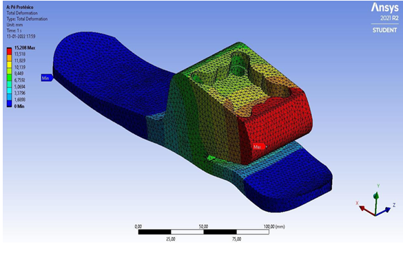
Figure 1. Total deformation (mm).
Figure 2 illustrates the Equivalent Stresses in MPa units. It is possible to observe the zone with higher stress in the material by the hotter red arrow and the zone with lower stress in the material by the hotter red arrow in the representation.
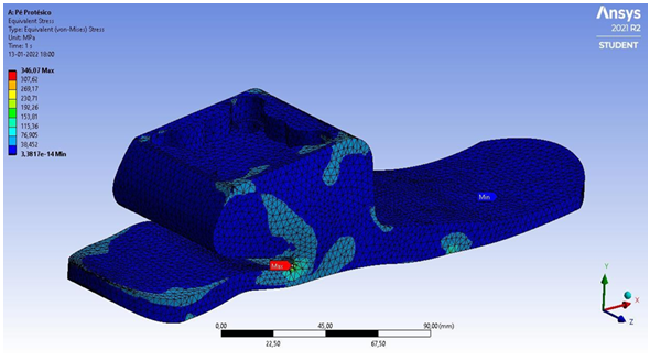
Figure 2. Equivalent stresses (MPa).
Figure 3 illustrates the Unitary Deformation in mm/mm units. It is possible to observe the zones with higher deformation by the red arrow in the representation.
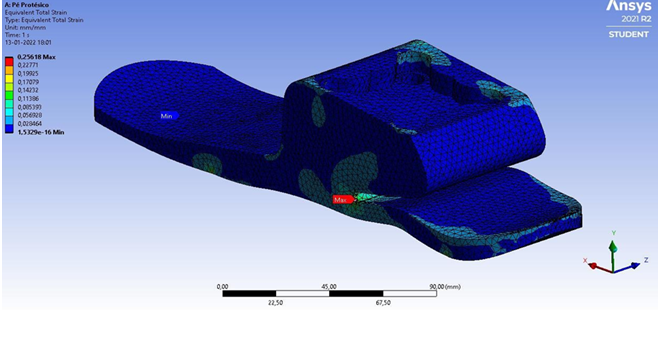
Figure 3. Unitary deformation (mm/mm).
Figure 4 illustrates the Cutting Stresses in MPa units. It is possible to observe the higher stress zones by the by the red arrow and the lower stress zones by the by the blue arrow in the representation.
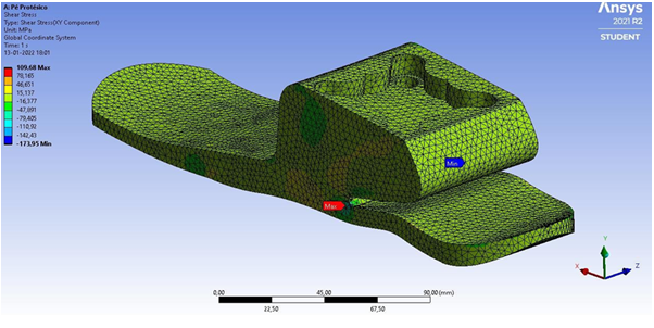
Figure 4. Cutting stresses (MPa)
Figure 5 illustrates the Safety Factor in nondimensional units. It is possible to observe the zones with higher deformation by the hotter colour representation.
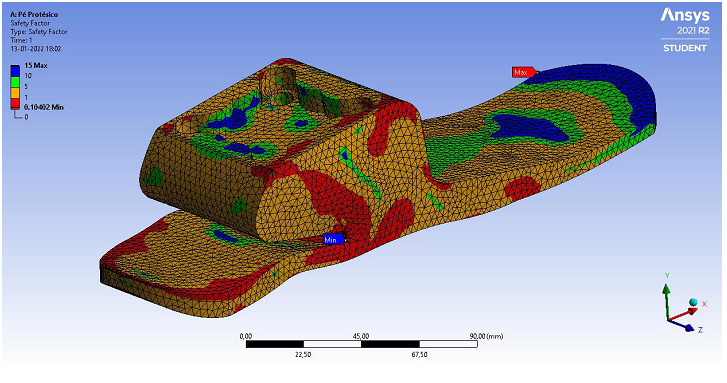
Figure 5. Safety factor (ad.).
4.2. Study 2
Study 2 uses Onyx + Carbon Fibers (rule of mixtures1) materials with the following characteristics:
- E=4.85 Gpa ; G=6.39 GPa; σ y=81 MPa; σ u=75.32 MPa
Figure 6 illustrates the Total Deformation in mm units. It is possible to observe the zones with higher deformation by the hotter colour representation.
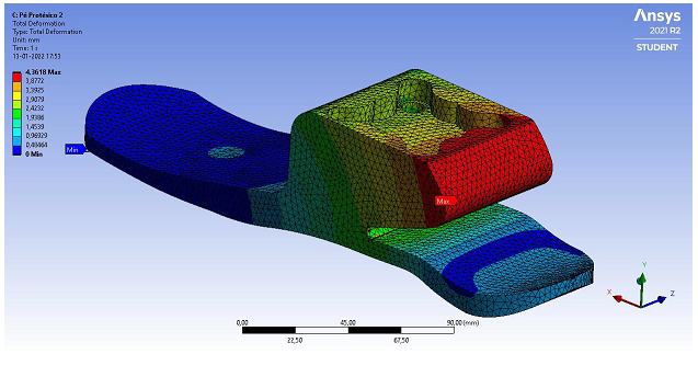
Figure 6. Total deformations (mm).
Figure 7 illustrates the Equivalent Stresses in MPa units. It is possible to observe the zone with higher stress in the material by the hotter red arrow and the zone with lower stress in the material by the hotter red arrow in the representation.

Figure 7. Equivalent stresses (MPa).
Figure 8 illustrates the Unitary Deformation in mm/mm units. It is possible to observe the zones with higher deformation by the red arrow in the representation.
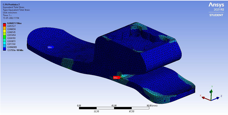
Figure 8. Unitary deformation (mm/mm).
Figure 9 illustrates the Cutting Stresses in MPa units. It is possible to observe the higher stress zones by the by the red arrow and the lower stress zones by the by the blue arrow in the representation.
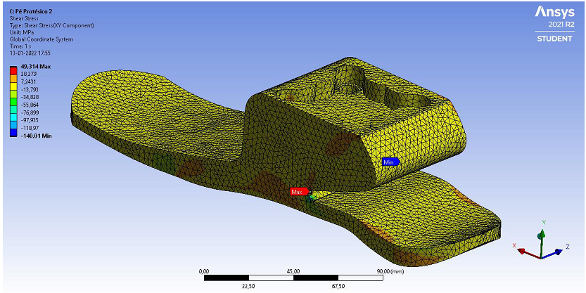
Figure 9. Cutting stress (MPa).
Figure 10 illustrates the Safety Factor in nondimensional units. It is possible to observe the zones with higher deformation by the hotter colour representation.
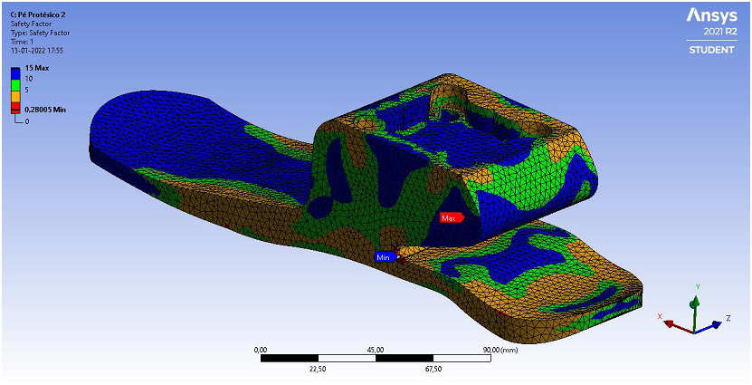
Figure 10. Safety factor (ad.).
4.3. Study 3
Study 3 uses Aluminum 6061-T6 materials with the following characteristics:
- E=69 Gpa ; G=25.95 GPa; σ y=259 MPa; σ u=313 MPa
Figure 11 illustrates the Total Deformation in mm units. It is possible to observe the zones with higher deformation by the hotter colour representation.
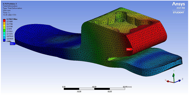
Figure 11. Total deformations (mm).
Figure 12 illustrates the Equivalent Stresses in MPa units. It is possible to observe the zone with higher stress in the material by the hotter red arrow and the zone with lower stress in the material by the hotter red arrow in the representation.
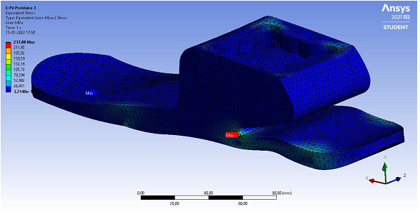
Figure 121. Equivalent stresses (MPa).
Figure 13 illustrates the Unitary Deformation in mm/mm units. It is possible to observe the zones with higher deformation by the red arrow in the representation.

Figure 13. Unitary deformation (mm/mm).
Figure 14 illustrates the Cutting Stresses in MPa units. It is possible to observe the higher stress zones by the by the red arrow and the lower stress zones by the by the blue arrow in the representation.
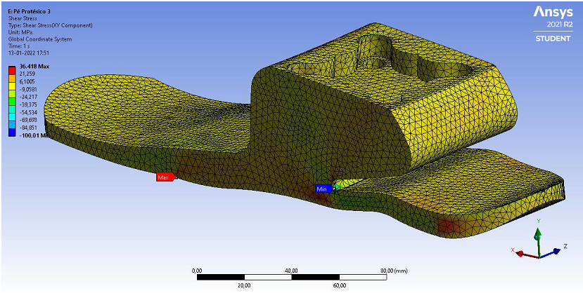
Figure 14. Cutting stress (MPa).
Figure 15 illustrates the Safety Factor in nondimensional units. It is possible to observe the zones with higher deformation by the hotter colour representation.
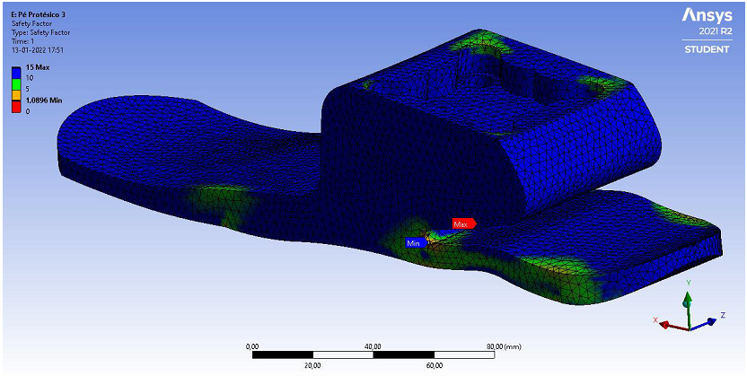
Figure 15. Safety factor (ad.)
4.4. Study 4
Study 4 uses Onyx + Carbon Fibers (rule of mixtures1) materials with the following characteristics:
- E=4.85 Gpa ; G=6.39 GPa; σ y=81 MPa; σ u=75.32 MPa
Figure 16 illustrates the Total Deformation in mm units. It is possible to observe the zones with higher deformation by the hotter colour representation.
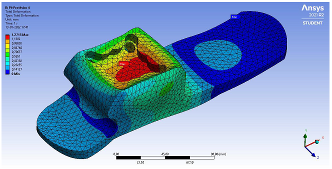
Figure 16. Total deformations (mm).
Figure 17 illustrates the Equivalent Stresses in MPa units. It is possible to observe the zone with higher stress in the material by the hotter red arrow and the zone with lower stress in the material by the hotter red arrow in the representation.
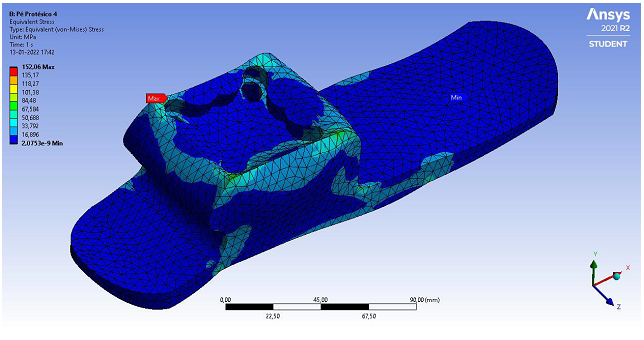
Figure 17. Equivalent stresses (MPa).
Figure 18 illustrates the Unitary Deformation in mm/mm units. It is possible to observe the zones with higher deformation by the red arrow in the representation.
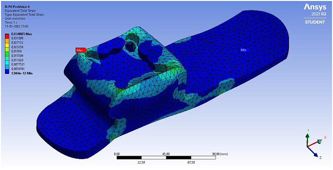
Figure 18. Unitary deformation (mm/mm).
Figure 19 illustrates the Cutting Stresses in MPa units. It is possible to observe the higher stress zones by the by the red arrow and the lower stress zones by the by the blue arrow in the representation.
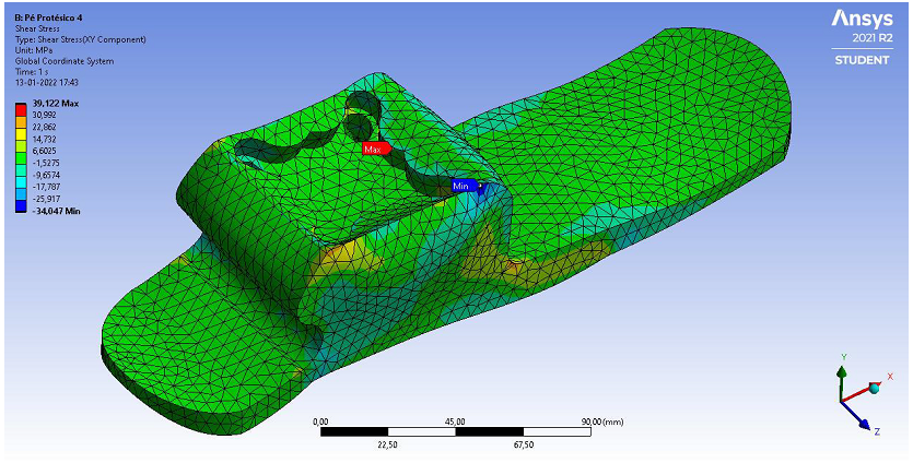
Figure 19. Cutting stress (MPa).
Figure 20 illustrates the Safety Factor in nondimensional units. It is possible to observe the zones with higher deformation by the hotter colour representation.
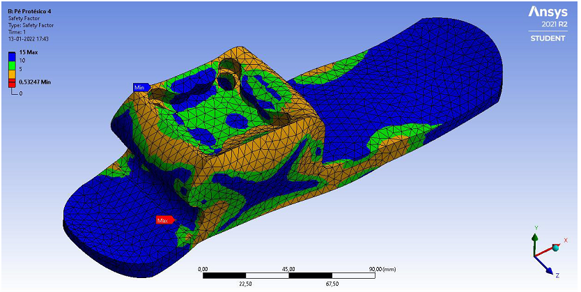
Figure 20. Safety factor (ad.).
4.5. Study 5
Study 5 uses Aluminum 6061-T6 materials with the following characteristics:
- E=69 Gpa ; G=25.95 GPa; σ y=259 MPa; σ u=313 MPa
Figure 21 illustrates the Total Deformation in mm units. It is possible to observe the zones with higher deformation by the hotter colour representation.
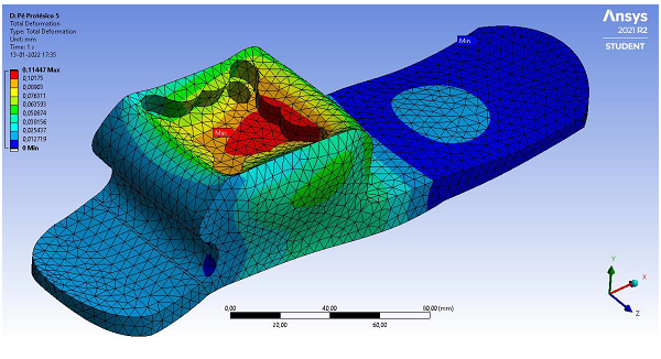
Figure 21. Total deformations (mm).
Figure 22 illustrates the Equivalent Stresses in MPa units. It is possible to observe the zone with higher stress in the material by the hotter red arrow and the zone with lower stress in the material by the hotter red arrow in the representation.
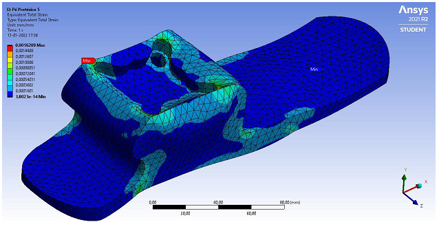
Figure 22. Equivalent stresses (MPa).
Figure 23 illustrates the Unitary Deformation in mm/mm units. It is possible to observe the zones with higher deformation by the hotter colour representation.
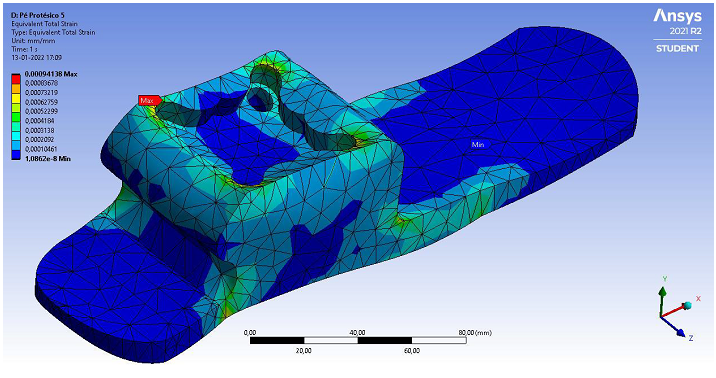
Figure 23. Unitary deformation (mm/mm).
Figure 24 illustrates the Cutting Stresses in MPa units. It is possible to observe the higher stress zones by the by the red arrow and the lower stress zones by the by the blue arrow in the representation.
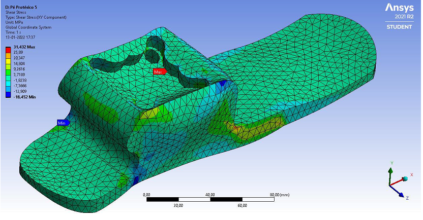
Figure 24. Cutting stress (MPa).
Figure 25 illustrates the Safety Factor in nondimensional units. It is possible to observe the zones with higher deformation by the hotter colour representation.
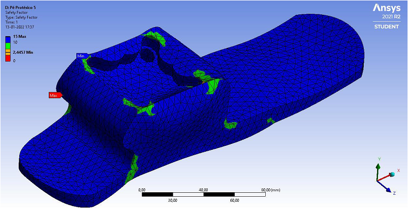
Figure 25. Cutting stress (MPa).
5. Discussions
Studies with model v5 show that there is not enough support in the heel area to transfer the load applied to the prosthetic foot to the ground.
In studies 1, 2 and 4 the models exceed the supply stress of the material (Safety factor less than 1).
The estimated deformations in all studies do not take into account the distribution of the load by filling the printed part. Therefore, deformations in actual tests should be considerably lower.
It is suggested to perform mechanical tests on the prosthetic foot, in order to measure the real mechanical resistance, and to be able to verify whether the results of these studies are close to a real situation (or not).
Studies with model v6 show a substantial reduction in deformations and stresses in the model, even with an increase in applied load (500 vs. 900 N).
The actual prosthetic foot, printed on Onyx and reinforced with continuous carbon fibre, will have mechanical strength to withstand loads higher than those applied in these studies, due to the distribution of the coals through the triangular filling structures.
6. Conclusions
Using simulations has the following main advantages:
- Decrease in the number of physical prototypes.
- Optimize production costs.
- Eliminate delays in prototyping.
- Facility for innovation.
- High quality end product.
It was possible to conclude that the simulations were meet in practice with amputee patient.
The low-cost prototype was easily adapted and well-adjusted to a real patient. The real tests in person proved that it is feasible to produce them with better quality of life.References
[1] C. Pastre, J. Salioni, B. A. Oliveira, M. Micheletto, and J. Netto Júnior, "Physiotherapy and transtibial amputation," Arch Science Health, vol. 12, pp. 120–124, 2005.
[2] D. Pereira, Development and testing of a prototype for application in patients with leg amputation. Braga: University of Minho, 2014.
[3] P. S. Selvam, M. Sandhiya, K. Chandrasekaran, D. H. Rubella, and S. Karthikeyan, Prosthetics for lower limb amputation. Intech Open: In Prosthetics and Orthotics, 2021.
[4] O. A. Chiriac and D. Bucur, "From conventional prosthetic feet to bionic feet. a review," Lecture Notes in Networks and Systems, vol. 143, pp. 130–138, 2020.Available at: https://doi.org/10.1007/978-3-030-53973-3_14.
[5] L. J. Claire, Rethinking modern prostheses in Anglo-American commodity cultures: Manchester University Press, 2017.
[6] H. Herr, G. P. Whiteley, and D. Childress, "Cyborg technology—biomimetic orthotic and prosthetic technology," Biologically Inspired Intelligent Robots, pp. 1–35, 2017.Available at: https://doi.org/10.1117/3.2068093.ch5.
[7] A. H. D. Announced, Development of an implantable medical device: College of Science and Technology, New University of Lisbon, 2014.
[8] J. P. Matos, E. Carolino, and R. Ramos, "Epidemiological data on amputations performed in Portugal between 2000 and 2015," in In IV Conference on Orthoprotesia, 2018.
[9] J. S. O. L. Lopes, "Development of sustainable transtibial prosthesis – Application of appropriate technologies. Port. Retrieved from: https://repositorio-aberto.up.pt/bitstream/10216/110237/4/227722.2.pdf," 2017.
[10] A. A. R. Campos, "Study of environmental effects and mechanical behavior of composite materials. University of Beira Interior. Retrieved from: https://ubibliorum.ubi.pt/bitstream/10400.6/2448/1/Tese_Completa_FinalAndréCampos.pdf," 2012.
[11] F. C. Campbell, Introduction to composite materials. In: Structural composite materials. Ohio: ASM International, 2010.
[12] M. R. Hossain, M. A. Islam, A. Van Vuurea, and I. Verpoest, "Tensile behavior of environment friendly jute epoxy laminated composite," Procedia Engineering, vol. 56, pp. 782-788, 2013.Available at: https://doi.org/10.1016/j.proeng.2013.03.196.