Reconnaissance for Weapon Detection and Enemy Order of Battle Awareness
B.Raj Narain1
L.Prabhu2
1Assistant Professor, Dept. of Electronics & Instrumentation Engineering, Velammal Engineering College, Chennai, India. |
AbstractObjective: This paper is about microbot for Reconnaissance (i.e. surveillance of the enemy border) which will provide early awareness of EOB (Enemy Order of Battle) to the army. The microbot will provide precise location and strength of the enemy troops. Methods: In this paper, descent control system module is used to glide the microbot to increase the time of flight. The microbot will launch using portable hand-held launcher. Telemetry receiver present in the microbot which will stream video on real time to GCS (Ground control station) is used. Findings: Physical parameters like altitude, pressure, temperature, speed, location will be transmitted to GCS. An active video module which consists of a wireless video transmitter and a pan-tilt mechanism driven by micro meters is used. Improvement: The video module is part of a miniature micro robot that is projected to areas of the environment to be surveyed. UAV microbot capable of analysis of data and real time video are featured. A perching mechanism using UAV is implemented on a < 350g flying platform which is integrated onto real flying microbot and successful perching maneuvers are illustrated as a proof of concept. |
Licensed: |
|
Keywords: |
1. Introduction
Unmanned Aerial Vehicles (UAVs) are defined as aircrafts without the onboard presence of pilots. UAVs have been used for surveillance and reconnaissance missions. UAVs have hence become a mainstay in current military operations providing combat troops and decision makers. The high power density batteries, long range and low-power micro radio devices, cheap airframes and powerful motors, UAVs have also become applicable in civilian circumstances like remote sensing, mapping, traffic monitoring, search and rescue, etc1.
An airplane can rotate about 3 axes (x, y, z) from the plane’s Cg. The position control of UAV is converted into angular control: roll (φ), pitch (θ) and yaw (ψ).. The main control surfaces or control inputs for a fixed wing UAVs may include some or all of the following:
a) Ailerons : to control the roll angle.b) Elevator : to control the pitch angle (up and down).
c) Throttle : to control the motor speed.
d) Rudder : to control the yaw angle (left and right).
Mini fixed-wing UAVs are highly dynamical and non-linear systems because of uncertainties caused by speed, altitude, weights, winds and turbulences. Rugged and efficient autopilot systems are hence necessary for reliable operation of the UAVs.
A UAV uses a set of sensors in conjunction with appropriate on-board algorithms to measure and/or estimate translational states (position and velocity) and rotational states (attitude and attitude rate).
Autopilots are used to guide the UAVs in flight with no assistance from human operators. The first developed for missiles are later extended the aircrafts and ships since in 1910s. The aircraft with its avionics radio transponders and payload is thus only a portion of the UAV, which as a system, also includes the ground control station and its user-interface software, antennas and radio transponders for both aircraft control and payload downlink4.
The main aim of this project is to build an Unmanned Aerial Vehicle for the purpose of reconnaissance .The UAV surveys the enemy troops in the military observation region. It is constructed with a DCS system, camera, wireless transmission module and a GPS tracking system.
The whole construction is made as microbot which weighs <350gms which is capable of capturing video of the enemy troops after it is launched in air using a launcher. It uses a micro camera to record the video at the time of descending towards the ground which is controlled by the DCS (Descent Control System).DCS use spoiler or parachute to control the descent action of the robot. The location of the robot can be traced using GPS and the data (roll, pitch, and yaw) from the microbot is transmitted using radio telemetry transmission module which works on 433 MHz frequency and covers a range of 2-4 km2.
The data that is transmitted from the microbot is received at the Ground Control Station and these are analysed using Mission planner software. The video that is captured by the microbot is recorded at the base station using Honestech TVR 2.5 software.
2. Microbot
Microbot is a miniaturized, sophisticated machine designed to perform a specific task or tasks repeatedly with high precision. Microbots typically have dimensions ranging from a fraction of a millimeter up to several millimeters. Microbot can be either autonomous or insect-like. Autonomous microbot contains its own on-board computer, which controls the machine and allows it to operate independently. The insect scheme is more common for micro robots. In an insect-micro robot arrangement, the machine is one of a fleet of several and identical units that are controlled by a single, central computer. (The term insect comes from the fact that such robots behave like ants or bees in a hive.). Advances in miniaturization could see every soldier carrying a micro robot with them as standard issue and also investigates the tiny automatons could offer for Intelligence Surveillance and Reconnaissance (ISR) and other tasks in areas too small or dangerous for humans to enter
The Advance in miniaturization have brought about a new generation of military robots are introduce a new range of capabilities. The small and light enough for an individual to carry and capable of squeezing undetected into otherwise inaccessible spaces, they can deliver ISR information to the operator and relay it to a command and control center.
The first fielded systems to benefit from the miniaturization trend are ground systems and are used in explosives reconnaissance and deactivation. The following hot in their footsteps, researchers are testing tiny robots that can fly and wiggle into unused spaces to capture data on enemy positions or locate survivors of natural disasters.
Microbot are designed spherical in shape which is of 150 to 350g weight and to that it has basic specification the microbot will provide precise location of the enemy troops.
Microbot have three layers:
b) Wire-less transmitter and receiver module of Data’s and Video. And coupled with power module to supply to the Microbot. (Middle layer)
c) Camera and GPS module (Lower layer)5.
These three layers are briefly discussed in Hardware specification.
The Microbot are used to transmit the data (roll, pitch and yaw) and video by wireless module. The purpose of using microbot in this project is to capture and transmit the video which contains the detailed information about the enemy troops and also the location can be tracked using GPS module which also gives the location of the enemy territory. After the robot is launched in Air module the robot will Descent towards the location of the enemy troops this action will be controlled by the DCS.The block diagram of Reconnaissance Robot shown below in Figure 1.
2.1. Launcher
This uses two CNC motors to drive friction wheels, of which the speed can reach 120km/h theoretically. The machine is strong because of its metal framework. The maximum no-load speed of the friction wheels could be close to 10000RPM, so that please be careful in your progress of testing. This launcher will be designed in Phase II of my project .Sample model of catapult type Ball launcher.
2.2. Ground Control Station (GCS)
The Ground Control Station (GCS) provides all capabilities in order to operate the unmanned Aerial vehicle systems. This includes mission planning, mission control and display of UAV status information, and UAV performance monitoring. The GCS allows both assisted flight mode and fully autonomous mode (GPS waypoints). The mission planner control allows all mission modifications on the field and planning all missions. In addition, several USB ports are available for mission download or upload the data. The main screen shows all UAV status information, while the second touch screen allows the selection of main UAV commands such as take-off, landing, or engine shutdown.
3. Hardware Description
3.1. Power Module
ArduPilot Mega Power Module uses XT60 Connectors and it also works with the ArduPilot Mega 2.5, ArduPilot Mega 2.6 side and top entry of Autopilots. It is quick and easy for providing the ArduPilot Mega 2.5 or 2.6 with a clean power supply from a LiPo battery; the power module monitors the current consumption and battery voltage through a 6-pos cable. The ArduPilot Mega Power Module consist of on-board switching regulator which supplies the output of 5.3V and at a maximum of 2.25 Amp's from LiPo batteries up to a 4S. The block diagram of Micro Robot is shown below in Figure 2.
3.2. Descent Control System
DCS is the most important part of microbot. The main aim of using this is to bring the descent rate to a value such that components are not affected by final impact with ground.
3.3. Wireless Module
Link 1
a) APM sensors have the LATLONG module, this sensor analyze the GPS and location of the microbot, height of the Microbot and estimates the heading of the Microbot (Direction of the Microbot).b) By the Data Tx and Rx we are able to get values in the mission planner software (GCS) using radio telemetry (433 MHZ) and it is connected to the laptop3.
Link 2
a) The APM 2.6 is used to feed the data to the Mini OSD.b) Video is given as input to OSD which superimposes the data (over relay) and send it to video Tx and from it the data is sent to AV Rx which is connected to mini OSD display or laptop. The Connection of Microbot (Inner Part) shown below in Figure 3.
3.4. Basic Wiring Diagram
The original Mini OSD’s power setup provides two stages to avoid noises coming from servos attached to your ArduPilot boards. These noises could introduce glitches on video signal6. The independent analog powering from a dedicated battery will heat the board, but the video is the clean as possible from MAX7456.The Layout Diagram of Mini OSD Connection shown below in Figure 4.
4. Software Description
4.1. Mission Planner
The Mission Planner for the ArduPilot open source autopilot project is a full-featured ground station application .This page contains information on the background of Mission Planner of this site layout.
The Mission Planner is a ground control station for Plane, Copter and Rover. It is compatible with Windows only. Mission Planner can be used as a configuration utility on a dynamic control for your autonomous vehicle. Here are just a few things you can do with Mission Planner6:
a) Load a firmware (the software) into the autopilot (APM, PX4…) that controls your vehicle.
b) The Setup, conFig, and tune the vehicle for optimum performance.
c) To Plan, save and load autonomous missions into you autopilot with simple point-and-click way-point entry on Google on other maps.
d) To Download and analyze mission logs created by your autopilot.
e) Interface with a PC flight simulator to create a full hardware-in-the-loop UAV simulator.
f) The appropriate telemetry hardware you can:
g) Monitor your vehicle’s status while in operation.
h) To Record telemetry logs which contain much more information the on-board autopilot logs.
i) View and analyze the telemetry logs.ji) To Operate your vehicle in FPV (first person view)
All of these and many features are covered in this section. The community documentation project for Mission Planner.
5.Outputs of the Mission Planner
Connection of Hardware Part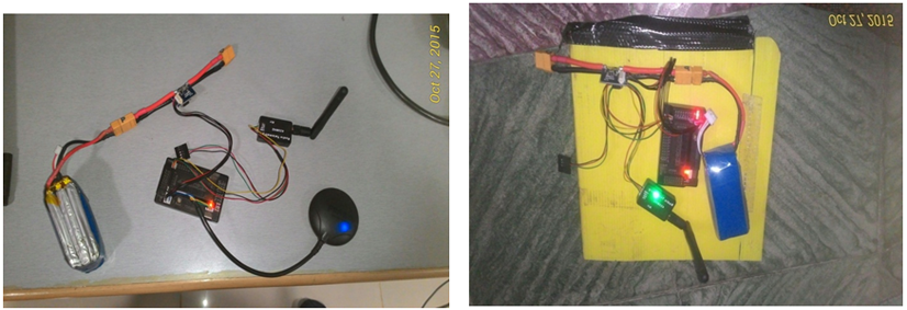
Figure-5. Connection of Hardware.
Output of Mission Planner
At Initial Position of the Microbot is shown in Figure 6.4.
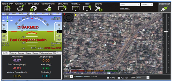
Figure-9. At Initial Position of the Microbot.
Rotate over Left of the Microbot is shown in Figure 6.5.
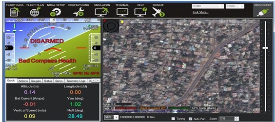
Figure-10. Rotate Over Left of The Microbot.
Rotate over Right of the Microbot is shown in Figure 6.6.
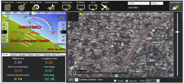
Figure-11. Rotate Over Right of The Microbot.
6. Conclusion
Hereby I conclude the interior connection of the microbot part using APM 2.6 ArduPilot to show the location of the microbot and with help of wire-less Telemetry module data and video information of enemy troops and the Output will be determined in MISSION PLANNER Software.
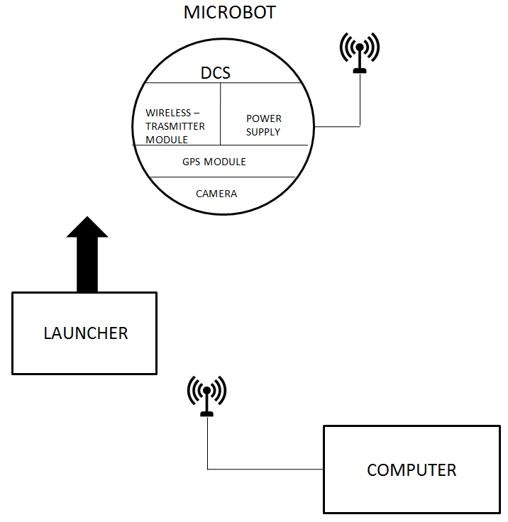
Figure-1. Main block diagram of Reconnaissance Robot.
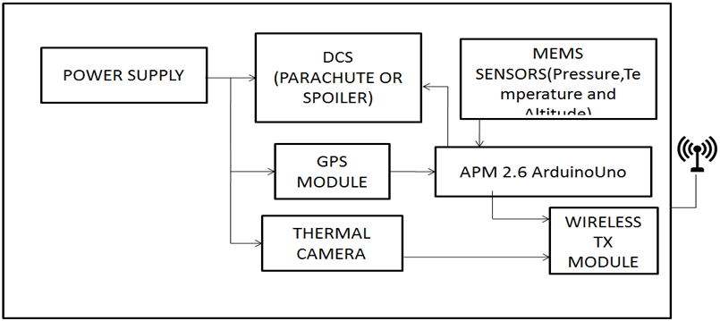
Figure-2. Block diagram of Micro Robot.
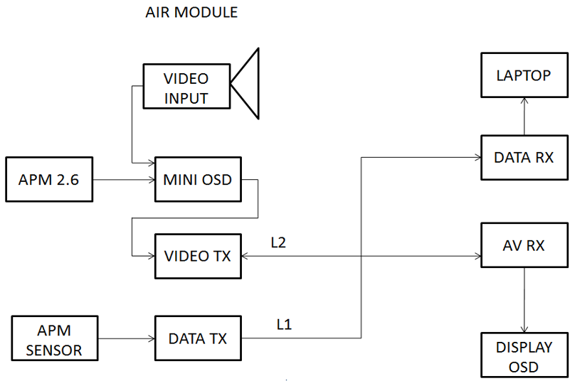
Figure-3. Connection Of Microbot (Inner Part).
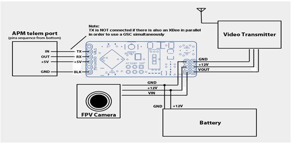
Figure-4. Layout Diagram of Mini OSD Connection.
References
[1] Kemal, Y. & Bradley, J. N. (2000). Active video system for a miniature reconnaissance robot, IEEE transaction on surveillance robot. Nikolaos P. Papanikolopoulos”, Richard Voyles”, Donald Krantz.Abstract O-78O3-5886–4/00/$ 10.00(C) 2000 IEEE 3919. 1.1. Launchable Reconnaissance Robots.
[2] Li, T.-J., Ge, M.-M. & Yuan, G.-W. (2012). Human activity recognition using radar and cameras on a mobile robot, in Industrial Electronics and Applications
[3] Green, W.E. & Oh, P.Y. (2003). An aerial robot prototype for situational awareness in closed quarters. IEEE/RSJ IntConJon Intelligent Robots and Systems, Las Vegas, NV. pp: 61-66.
[4] Gauthier, S. S. & Chamma, W. (2004). Surveillance through concrete walls. In Sensors, and Command, Control, Communications, and Intelligence (C3I) Technologies for homeland security and homeland defense III. International Society for Optics and Photonics, 5403: 597-609.
[5] Micro-camera for Surveillance, (n.d). European convention on security and detection, IEE, London, UK. pp: 50-53.
[6] Anderson, J.D. (1999). Aircraft performance and design, McGraw-Hill. Barrows, G., Neely, C. (2000). Mixed-mode VLSI Optic Flow Sensors for In-flight Control of a Micro Air Vehicle. Proc. SPIE, 4109: 52-63.